Arduino Hello World
I recently received an Arduino UNO R3 as a gift, bundled with a kit of sensors and components. I wanted to see if I could get a decent development workflow going on my Chromebook.
Since Chromebooks often have limited storage, I chose to skip the heavy IDE (150+ MB) and instead just install the Arduino CLI. Compared to the Arduino IDE I have installed on my workstation, I don't see a compelling difference
The Hardware
For this little project, I have:
- In the kit
- Arduino UNO R3
- Breadboard and leads
- various resistors (including 220-ohm)
- RGB LED (common cathode)
- USB A to USB B cable
- Lenovo Chromebook
- USB C (plug) to USB A (socket)
Installing Software
I basically followed this guide which is likely to be more up-to-date and correct than mine, but here's what I did to install the CLI
Download and run the install script
curl -fsSL https://raw.githubusercontent.com/arduino/arduino-cli/master/install.sh | shLink to the binary (since I didn't install it in the bin folder)
sudo ln ./bin/arduino-cli /usr/binInstall the core for the board I have
arduino-cli core install arduino:avr
Enabling the USB device
To enable the Linux container in ChromeOS to see the USB device, go to the Terminal Settings and enable the Arduino USB device.
VSCode Tasks (all optional)
Typing out CLI commands every time you want to test a change is tedious. I'm using VS Code's tasks feature to automate the process.
Create the file.vscode/tasks.json with a command to build and one to upload. We can add more to this later (such as serial monitoring)
{
   "version": "2.0.0",
   "tasks": [
       {
           "label": "Arduino Compile",
           "type": "shell",
           "command": "arduino-cli compile --fqbn arduino:avr:uno ${fileDirname}",
           "group": {
               "reveal": "always",
               "kind": "build",
               "isDefault": true
           }
       },
       {
           "label": "Arduino Upload",
           "type": "shell",
           "command":"arduino-cli upload -p /dev/ttyACM0 --fqbn arduino:avr:uno ${fileDirname}"
       }
   ]
}
Running them in vanilla VSCode
Now I can use these to build and upload:
ctrl+shift+bto compilectrl+shift+pto open the menu >Tasks: run task>Arduino: upload
Tip: I later used the Tasks extension by actboy168, which puts these buttons right in the status bar at the bottom of the screen.
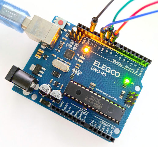
"Hello World" Blinking LED
I created the following uno.ino which flashes the built-in LED (on for 800ms, off for 200ms) in a loop. Using the tasks I set up, I compiled then uploaded the code.
void setup(){
   pinMode(LED_BUILTIN, OUTPUT);
}

void loop(){
   digitalWrite(LED_BUILTIN, HIGH);
   delay(800);
   digitalWrite(LED_BUILTIN, LOW);
   delay(200);
}
Okay, that worked fine. Let's bust out the breadboard and an RGB LED
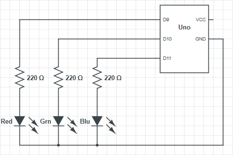
RGB LED Cycling
This project uses the digital pins 9, 10 and 11, and the function "analogWrite" which outputs a PWM signal with varying "on" time, which has the effect of controlling the brightness
This plot shows how the r, g, and b variables changes as hue progresses through the range 0 to 360. At any point within that range, the sum of the 3 channels adds up to 120.

I found that lowering the brightness of my LED means that its not so blidingly bright, but you can manage this with resistors too.
The Circuit
My circuit looks like this (for me the red, green and blue LEDs are part of an RGB LED):
The Code
// Set up constants
const int PIN_RED = 9;
const int PIN_GREEN = 10;
const int PIN_BLUE = 11;
const float BRIGHTNESS = 0.2;
const float MULTIPLIER = 255.0 / 120.0 * BRIGHTNESS;

int hue = 0;

void setup(){
    pinMode(PIN_RED, OUTPUT);
    pinMode(PIN_GREEN, OUTPUT);
    pinMode(PIN_BLUE, OUTPUT);
}

void loop(){
    const int r = 120 - min(120, min(abs(hue), abs(hue - 360)));
    const int g = 120 - min(120, abs(hue - 120));
    const int b = 120 - min(120, abs(hue - 240));
    // Normalise the total brightness to a range from 0-255, then dim it a bit
    analogWrite(PIN_RED,   (int)(r * MULTIPLIER));
    analogWrite(PIN_GREEN, (int)(g * MULTIPLIER));
    analogWrite(PIN_BLUE,  (int)(b * MULTIPLIER));
    // Delay by 24ms, then increment hue (resetting at 260)
    delay(24);
    hue = (hue + 1) % 360;
}
Wrapping Up
Setting this up was a great way to get started with the Arduino CLI. Even on a modest Chromebook, the experience is snappy and lightweight to get going.